
Insights
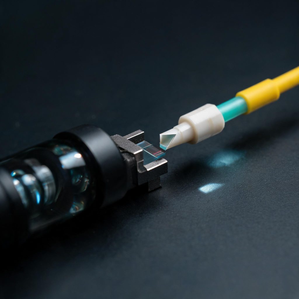
Right-Angle Prism Integration: Approve the Beam Route and Image Orientation Together
OPTICS · TECHNICAL INSIGHT
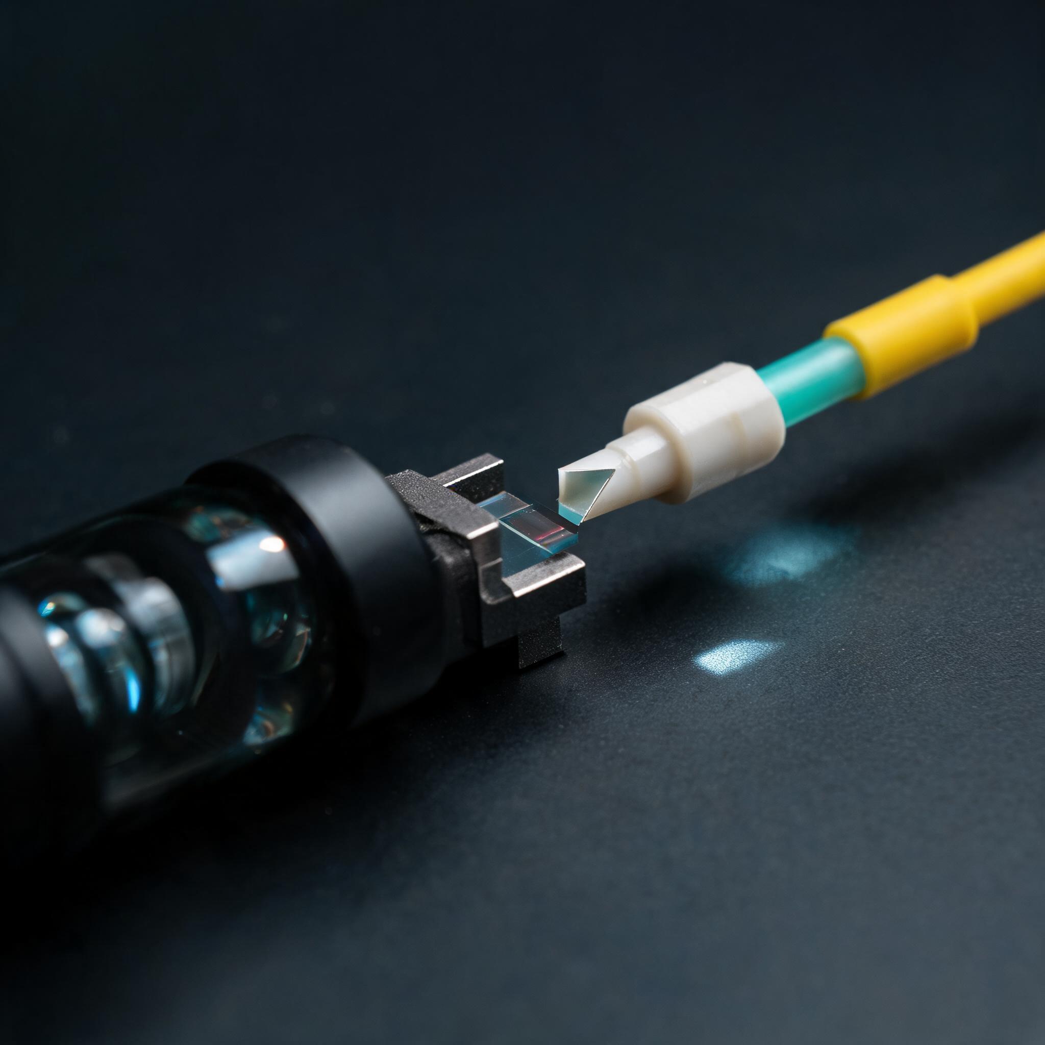
A right-angle prism should be approved against a marked beam route, not only its edge dimensions. Identify entrance, exit and reflection faces, then confirm image orientation in the installed configuration before releasing the assembly.
Reference and scope
This is an original TUOLAN technical insight supported by the official technical reference linked below. It is not a new product announcement. The application recommendations are TUOLAN’s analysis; supplier examples are not TUOLAN performance guarantees.
Draw the ray path before assigning coated faces
Edmund Optics’s prism examples describe different beam deviations according to the optical route. This is why the name “right-angle prism” does not by itself specify every face’s function.
For custom optical prism sourcing, mark the entrance and exit apertures, nominal ray direction and intended reflecting face on the assembly drawing. State whether the design relies on total internal reflection or a reflecting coating. Ask the designer to review the material, wavelength, ray angles and external medium together.
Check the image with an asymmetric target
An angular beam-path check does not prove that the delivered image has the required handedness or rotation. Use an asymmetric target with a clearly marked direction, and record the resulting image at the final sensor or viewing plane. Include the actual prism orientation and any other reflections in the train.
Retain the drawing and target result with sample approval. This makes a later integration change easier to distinguish from an incorrectly oriented component.
Make the coating drawing face-specific
When requesting prism optical coatings, label each face and separate transmission from reflection requirements. Do not apply an antireflection specification indiscriminately to every surface.
Define how the carrier holds the prism, including contact locations and permitted adjustment. Verify that mounting, bonding or nearby surfaces do not alter an interface on which the design depends. Final acceptance should connect the marked optical route, image result and mechanical configuration rather than approve three unrelated documents.
Buyer RFQ checklist
- Label entrance, exit and reflecting faces on one controlled drawing.
- Verify handedness and rotation with an asymmetric image target.
- Specify coatings and mounting contact separately for each face.
Review your project specification
Send the application, drawing or interface requirements, target quantity and market to TUOLAN TRADE or sales@tuolango.com.
Sources
Official company source, Technical reference; publication date not stated. Reviewed 14 October 2026. Checked on 14 October 2026. Buyer recommendations are TUOLAN’s analysis, separate from the source announcement.
Edited and analysed by TUOLAN TRADE.